


Introduction
An abnormal femoral anteversion angle is associated with a variety of clinical problems ranging from in-toeing gait in early childhood to disabling osteoarthritis of the hip and knee in adulthoods. Accurate evaluation of femoral anteversion is essential to inform the decision for surgical correction. In children, the indication for surgery is an age of eight years or older with the measured anteversion above 50 degrees and medial hip rotation above 85 degrees [1].
Many imaging methods have been used to measure femoral anteversion, such as two-dimensional (2D) computed tomography (CT), magnetic resonance (MR) or ultrasound (US) imaging, and three-dimensional (3D) modeling [2-9]. More recently, measurement of axial-oblique reformations parallel to the long axis of the femoral neck was introduced and reported to lead to more accurate measurement of femoral anteversion than conventional 2D imaging [10-12]. However, there is still no consensus on the imaging modality of choice.
This study aimed to define a more accurate CT scanning method for measurement of the anteversion angle of the femoral neck.
Materials and methods
Five models of the femur, consisting of three models of saw bones and two of cadaveric bones, were used to measure femoral anteversion.
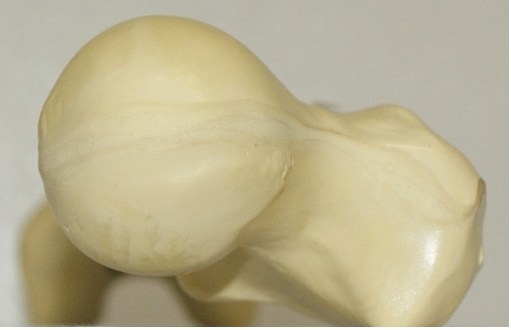
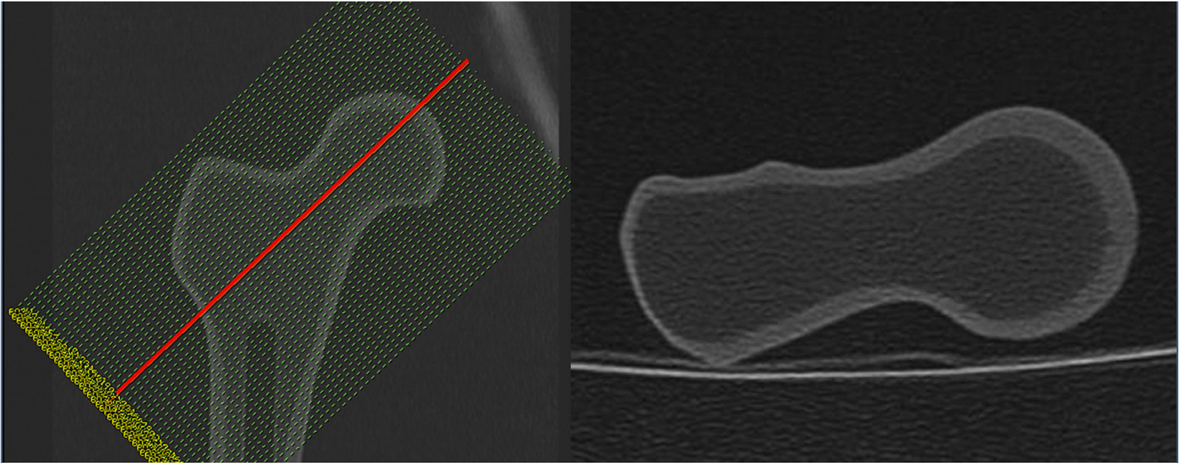
Photographs of all five bone models were taken from the superior aspect of the femoral neck after placement of the specimen at the edge of the table on the horizontal surface, such that the inferior end of both femoral condyles rested on the surface of the table. For measurement of the real femoral anteversion, the specimen was placed parallel to the mechanical axis such that that the center of the femoral head and center of the intercondylar notch were aligned in a single line (Fig. 1). Two different CT scans were obtained. The first was a single transverse sectional image of the femoral neck as it passes just below the inferior border of the femoral head (CT1), as described by Sugano et al. [13]. The second was an axial-oblique image parallel to the long axis of the femoral neck (CT2), as described by Tomczak [10] (Fig. 2,3). In addition, we obtained another image in which the posterior surface of the medial and lateral condyles was clearly visible, and femoral anteversion was measured in each series (Fig. 4).
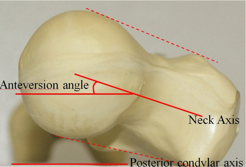
Two major axes, the neck and posterior condyle, were used as reference lines and defined as follows. The neck axis was defined as the center line drawn between two lines tangential to the upper and lower surfaces of the femoral head (or the most proximal portion of the inferior neck just below the inferior border of the femoral head on CT1) and greater trochanter (Fig. 5). The posterior condylar axis was defined as the line connecting the most posterior surfaces of the both femoral condyles. In photographs, the horizontal surface represented the posterior condylar axis. The femoral anteversion angle was defined as the angle between the neck axis and the posterior condylar axis (Fig. 5).
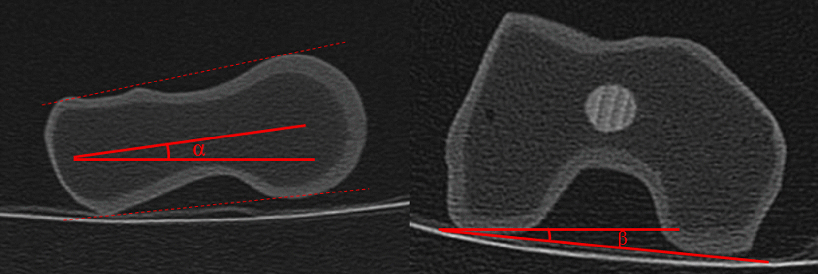
All photographs and CT images were printed, and the femoral anteversion angle was measured by manually in accordance with the Kingsley Olmstead [14] method using a goniometer, ruler, and pen with the same reference lines. The angle (alpha) between the neck axis and horizontal reference line, and the angle (beta) between the posterior condylar axis and horizontal reference line were measured separately by the method of Tomczak [10] (Fig. 6). The femoral anteversion angle was calculated by either adding or subtracting the beta angle from the alpha angle, according to the rotation type. All measurements were repeated three times with at least a 1-week interval between measurements by each of three experienced orthopedic surgeons, to identify intra- and inter-observer variability of the techniques. Each of three doctors measured all anteversion angles with blinding from their previous records and results of other doctors. A total of 45 measurements were obtained and used for statistical evaluation. Intra-observer bias, inter-observer bias, and the results of the two different CT methods were evaluated and compared with the results from the actual photographs through intraclass correlation coefficient (ICC) tests. All analyses were performed with SPSS version 2.0.
Results
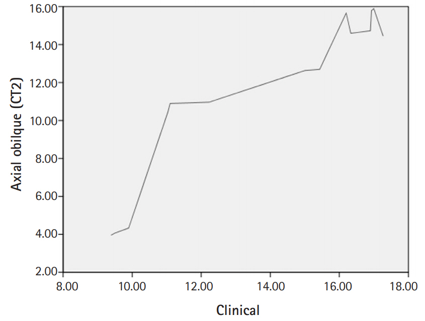
The femoral anteversion angles of each of the five bone models, as measured three times by each observer, were used to assess intra-observer bias. The ICC test revealed no evidence of intra-observer bias (ICC ≥ 0.952) (Table 1). The average value of the femoral anteversion angle measured by the three observers was used to evaluate inter-observer bias. The ICC test revealed no evidence of inter-observer bias (ICC ≥ 0.993) (Table 2). Fifteen measurements (average of three measurements for each observer in the five bone models) for each CT method were evaluated and compared with measurements from the actual photographs through ICC tests. The femoral anteversion angle measured on the photos was significantly correlated with the femoral anteversion angle measured on each type of CT scan (Table 3). However, CT 2 more closely approximated the clinical method than CT1. (ICC, CT1 = 0.824, CT2 = 0.937) (Fig. 7,8).
Discussion
The femoral anteversion angle can be defined as the angle formed by the femoral condyle plane and a plane passing through the center of the neck and femoral head. If the femoral condyle plane passes behind the center of the femoral head, neck anteversion is present [8].
On the basis of measurements from 630 dry anatomic femoral specimens, Kingsley and Olmstead reported that the mean femoral anteversion angle was 8.0° (range, -20° to 38°). Usually, the mean femoral anteversion angle is higher in infants (mean, 24.4°; range, -10° to 64°) and children (mean, 17.2°; range, -4.5° to 38°) than adults, but the angle gradually diminishes during childhood and adolescence [14].
Rotational problems, when outside of the normal range, are referred to as torsional deformity, and these deformities are relatively common in infancy and childhood. In the vast majority of children, torsional deformities of the lower limb improve spontaneously [1]. However, clinical disability can introduce cosmetic and functional problems, such as in-toeing gait in early childhood, which can lead to disabling osteoarthritis of the hip and knee in adults if they persist.
Abnormal femoral anteversion is correctable by rotational osteotomy, but the operation should be performed only in children after the age of eight if they still have an abnormal anteversion angle greater than 50 degrees and medial rotation of the hip greater than 85 degrees [1]. Therefore, precise measurement of the real femoral anteversion angle is needed to inform the decision for surgical correction.
Although direct anatomic measurement of the real femoral anteversion angle is desirable, it may not be possible in clinical settings. Consequently, other accurate and reproducible methods for measuring the femoral anteversion angle have been investigated [2-9]. However, these studies have shown that measurements can vary according to the observer’s experience, imaging modality, measurement method, and reference line [6,8,13,15-18].
CT techniques using single or multiple axial slices are generally favored for the measurement of femoral anteversion, but these methods show variable accuracy because the femoral neck is not perfectly cylindrical, and the neck-shaft angle is not always 90 degrees. The accuracy of a single transverse sectional image can be significantly affected by its level on the femoral neck [13]. Anteversion is often underestimated by more proximal sections and overestimated by more distal sections.
To overcome the limitations of conventional 2D imaging methods, researchers have developed a 3D imaging method, and satisfactory results have been reported [8,9]. However, 3D imaging has several drawbacks: 3D rendering is time consuming and costly. Although 3-D CT is a valuable diagnostic tool in evaluating bony femoral anteversion, it has several limitations such as radiation exposure [19], inefficiency in use in terms of time and technical effort, and high cost. Severe deformity of the femoral head or neck-shaft angle or an inappropriate position makes it difficult to obtain 3-D reconstructed images, but the 2-D CT technique exhibited excellent reliability and clinically acceptable accuracy [20].
Several studies have recommended the assessment of axial-oblique reformations parallel to the long axis of the femoral neck using axial CT slices. Tomczak et al measured femoral anteversion angle through the MR image that showed the centers of the head and femoral neck and therefore allowed visualization of the true neck axis by calculating the angle between true neck axis and horizontal reference line [10]. This method has been reported to improve the accuracy of femoral anteversion measurement compared with conventional 2D imaging methods [10-12]. The technique allows for accurate anteversion assessment regardless of patient positioning [11], it and does not require 3D rendering.
CT imaging using the conventional transverse section and the axial oblique section are among the most widely used and cost-effective methods to measure femoral anteversion. However, there is still no consensus on the imaging modality of choice. Sugano et al. found that the transverse section through the most proximal portion of the inferior neck (excluding the head) provides the most accurate estimate of the femoral neck axis [13]. Other authors have suggested that 3D imaging provides more accurate and reliable measurements of femoral anteversion than 2D imaging, and femoral anteversion can be analyzed quantitatively using 3D-CT regardless of patient position [8,9]. More recently, Parikh and Noyes [12] reported that axial oblique images show the closest approximation to true femoral anteversion. However, to our knowledge, no study in the orthopedic literature has compared these techniques with an anatomic reference considered to be the most accurate method for the measurement of femoral anteversion.
Thus, we aimed to determine a more accurate CT method to measure the real femoral anteversion angle by comparing conventional (axial) and axial-oblique CT scans with actual clinical photographs of human cadaveric and saw bone femurs. The femoral anteversion angle measured by the axial-oblique image (CT2) more closely approximated that of the clinical method than did the conventional transverse sectional image (CT1). This finding is consistent with that of Parikh and Noyes [12]. The axial-oblique technique showed good reproducibility with low inter-observer variation (ICC = 0.999) and intra-observer variation (ICC ≥ 0.993). These results might have been affected by the reference lines used in our study. We defined the neck axis in a slightly different way than other studies. Because the shape of the femoral neck is elliptical, and the shape of the femoral head in a sectional image is not a perfect circle, determining the centers of the femoral head and neck can vary according to the observer.
It should be noted that our study did not include pediatric femora. Because many hip conditions that require clinical knowledge of femoral anteversion occur in children, evaluation of another femoral model that included pediatric femora may have lent more predictive power to our findings. We also did not evaluate a 3D imaging method because of the difficulty of determining the centers of the femoral head and neck derived from the process that converts the 2D image into the 3D reconstruction image.
The axial-oblique technique was reproducible and showed greater accuracy in the measurement of femoral anteversion than the single transverse sectional technique. Application of these data to a clinical setting should be carried out sensibly, recognizing that confounding factors such as accompanying disease (e.g., cerebral palsy), variability in technician skills, and radiographic interpretation by clinicians may lead to errors in accurate measurement of femoral anteversion